
As noted previously, I’m working on a project similar to Ben Eater’s 8 bit breadboard project (see eater.net). This time around, time keeping.
While it’s probably possible to build a computer without a clock and have it work, it’s quite a lot easier to keep things from going off the rails with some sort of time keeping. To do that, I need a clock module. The design of this one is essentially Ben’s design with some adjustments. (Edit: do take a look at MiaM’s comment below for a rather significant pitfall depending on your use case.)
Basically, it has four main parts. First is a push button with a 555 timer used to debounce it. Second is a variable rate automatic clock run by, get this, a 555 timer. Then there is a slide switch to select between manual and automatic modes running through another 555 timer. This is pretty much exactly Ben’s design. Finally, there is some glue logic that leads to two outputs: CLK (positive clock) and !CLK (negative clock). There is also an input, HALT, which when high will stop the clock.
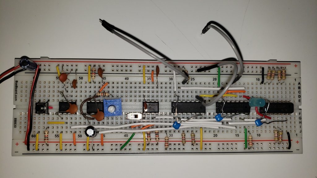
In the image above, the pushbutton and associated 555 timer is on the left. The adjustable oscilator and its associated timer are next to it. Then the mode slide switch and its 555 timer. The remaining three chips are a 74LS04 Hex Inverter, of which 3 gates are used, a 74LS08 Quad And gate which is fully used, and a 74LS32 Quad Or gate of which 1 gate is used. You can see the decoupling capacitors for each chip overtop of the chips themselves. The blue LED will show the state of the CLK output.
The CLK output is fed through an And gate with both inputs tied together. This is a quick way to create a buffer for the output which should ensure a clean output signal to the bus. It also adds a gate delay similar to the inverter on the !CLK output, which should also ensure a clean output signal. The two clock outputs are the jumpers that are not connected. The jumper connected across to ground is the HALT input. CLK and !CLK will be fed to the bus which HALT is a control signal that will ultimately be provided by the control logic when it is created. There is no significance to the colour of the wires.
I have included a schematic of the module below (assuming I didn’t make any errors creating the schematic). It’s in SVG format so you should be able to scale it up to read it. As far as I can determine, it works though I haven’t put a scope on CLK output to see how clean it is.

Beware that this circuit can potentially cause a CPU to crash.
When switching between oscillator and one step mode there is nothing that makes sure that every half-wave of the output signal is long enough.
The chance of having problems due to this is low at lower oscillator frequencies, but even at a few hundred Hz it will likely eventually happen and when it happens there is a risk of you scratching your head trying to figure out what went wrong and not even suspecting the oscillator to be a part of the problem as it seemingly has worked flawlessly for a long time.
(I haven’t checked out Bens homebuilt CPU – but this clock generator is what he used for the 6502 breadboard project and IMHO the clock generator is really the part that could do with improvements)
I was aware that there were issues with the design and I had noticed the partial wave depending on the time of switching. I haven’t put a lot of thought into how to redesign it at this point though I have an idea or two. I’m using this scheme currently because it works well enough at “human” frequencies so I can make some progress with other stuff.
It’s definitely good to have a note about the potential lurking dragons, though.
Ben does seem to have a great deal of luck in running marginal stuff and having it work, though. Like how he was able to connect an RC edge detector to directly to the clock line with no buffer or other measures and not have it feed back to the other stuff connected to the same clock.
http://pwillard.com/?p=411 My solution to simplifying Ben’s Clock Module